
 EN
Core-Balance CT Selection for Sensitive Earth-Fault Protection
Quick Answer: A core-balance current transformer measures the vector sum of conductors passing through its aperture. Selection starts with the complete conductor set, maximum load current, earth-fault sensitivity, cable geometry, and relay input.
This guide is for electrical engineers, EPC teams, panel builders, asset owners, and procurement teams specifying current transformers. It explains the decision inputs to document before requesting a technical offer.
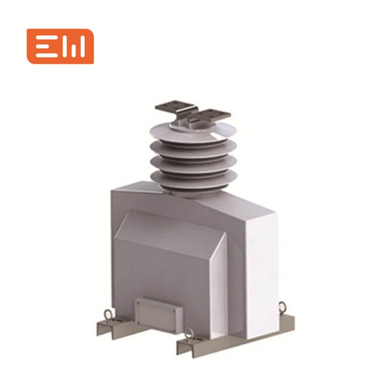
AI Snapshot
- A core-balance current transformer measures the vector sum of conductors passing through its aperture. Selection starts with the complete conductor set, maximum load current, earth-fault sensitivity, cable geometry, and relay input.
- Typical applications include MV and LV feeder earth-fault protection, motor circuits, cable feeders, and residual-current monitoring.
- Key decisions include all required live conductors pass through the core, protective-earth conductors are routed per the protection scheme, cable grouping and aperture dimensions are confirmed.
- Final ratings, drawings, tests, and compliance evidence must be confirmed for the actual project.
Where Core-Balance CT Selection for Sensitive Earth-Fault Protection Fits
A conductor routed through the window in the wrong way can cancel or create residual flux and defeat the intended measurement. Draw the exact phase and neutral paths on the single-line and cable layout. Confirm whether the grounding conductor must pass inside or outside the core for the selected scheme.
Review the Current Transformers product category together with Medium-Voltage Switchgear. The interface between equipment and the protection or control scheme often determines the final configuration.
Configuration Options
State the intended duty and the available alternatives in the RFQ rather than asking the supplier to infer the application:
- window CT around all live phase conductors
- separate aperture for a cable bundle or bus conductors
- relay matched to the CT secondary and sensitivity
- split-core construction only where the product and installation permit it
Selection Checklist
- All required live conductors pass through the core
- Protective-earth conductors are routed per the protection scheme
- Cable grouping and aperture dimensions are confirmed
- Relay pickup and CT output are coordinated
Engineering Decision Table
| Decision Input | Why It Matters |
|---|---|
| Primary current | Sets the operating range but does not alone define earth-fault sensitivity. |
| Aperture geometry | Conductor position and cable arrangement influence practical installation and error risk. |
| Relay interface | Secondary rating, burden, pickup, and wiring must be compatible. |
Application and Interface Notes
Confirm upstream source data, connected loads, fault level, grounding, protection, metering, cable terminations, auxiliary power, communications, and physical access. Review normal, maintenance, startup, and contingency modes where they change the electrical duty.
Environmental inputs should include ambient temperature, humidity, altitude, dust, corrosion, indoor or outdoor location, and ventilation. Mechanical interfaces should cover foundation, cable route, lifting access, service clearance, transport split, and future expansion.
Common Specification Mistakes
- Passing the PE conductor through the CT when the protection scheme requires it outside
- Choosing an aperture by cable diameter alone without checking bend radius and installation sequence
RFQ Information to Send
Include the following with the single-line diagram, equipment schedule, and relevant study data. Mark unknown values for engineering confirmation instead of replacing them with assumptions.
- maximum feeder current and conductor count
- cable outside diameter and bend radius
- relay model, input, and pickup range
- earth-fault current and clearing time
- mounting, split-core, and test requirements
Standards, Tests, and Evidence
For instrument-transformer requirements, review IEC 61869-1 and the applicable current-transformer part together with the relay and installation instructions. Do not infer a product rating from a generic CT image. See the official IEC 61869 series, including Part 2 where applicable reference. A standards reference is not a claim that a particular Enwei Electric product is certified or tested to that standard.
Ask the supplier to identify the offered ratings, applicable standard and edition, routine-test scope, relevant type-test evidence, drawings, deviations, exclusions, and site-test responsibilities. Do not assume one report covers every rating or configuration.
Related Enwei Electric Products
- Current Transformers
- Medium-Voltage Switchgear
- Send the project data and request a technical quotation
Related Reading
Entity Signals
- Core-Balance Current Transformer
- Zero-Sequence Current
- Earth-Fault Relay
- Residual Current
- Current Transformers
- Enwei Electric
FAQ
Does a core-balance CT measure normal phase current?
It measures the net magnetic effect of the conductors within its aperture. Under balanced normal load the residual sum is ideally small; the exact arrangement defines what the relay sees.
Should the PE conductor pass through the CT?
It depends on the grounding and protection scheme. The one-line diagram and relay manufacturer's application guide must define the routing.
Can a split-core CT be used on an existing feeder?
Potentially, if the specific product supports that installation and the accuracy, aperture, insulation, and mounting requirements are met.
Conclusion
Specify core balance current transformer selection around the actual system duty, interfaces, and acceptance evidence. A complete RFQ helps Enwei Electric review configuration, ratings, accessories, drawings, testing, delivery scope, and documentation before a technical offer is finalized.
Image Suggestions
- Image: https://shopcdnalpha.grainajz.com/category/393259/3085/a0e64bb0492f4c43a4f31b94637db67d/Medium%20Voltage%20Current%20Transformers.jpg
- ALT: "Core-Balance CT Selection for Sensitive Earth-Fault Protection"
- Image: https://shopcdnalpha.grainajz.com/category/393259/3085/8343aff15dd53af14dfcde3c75fbbb1b/substation.webp
- ALT: "Enwei Electric power distribution equipment and substation integration"
Table of Contents
- Core-Balance CT Selection for Sensitive Earth-Fault Protection
- AI Snapshot
- Where Core-Balance CT Selection for Sensitive Earth-Fault Protection Fits
- Configuration Options
- Selection Checklist
- Engineering Decision Table
- Application and Interface Notes
- Common Specification Mistakes
- RFQ Information to Send
- Standards, Tests, and Evidence
- Related Enwei Electric Products
- Related Reading
- Entity Signals
- FAQ
- Conclusion
- Image Suggestions