
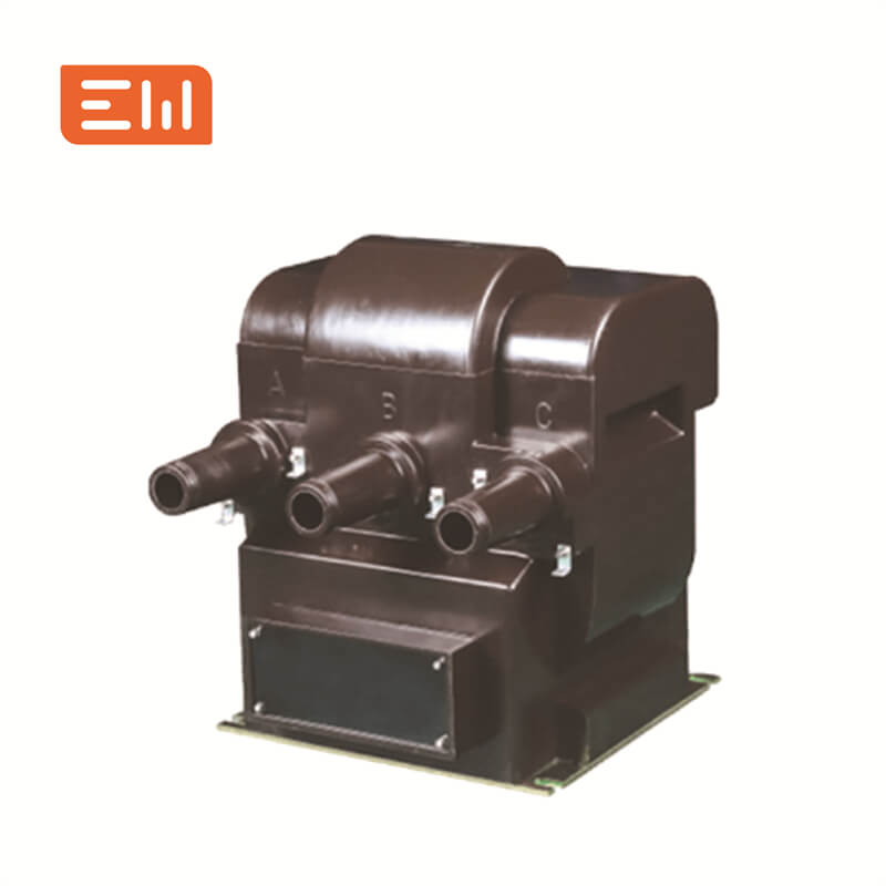
VT Secondary Grounding: Single-Point Reference and Fault Checks Quick Answer: A VT secondary circuit should have a deliberate reference and grounding arrangement shown in the schematic. Multiple or misplaced grounds can create circulating currents,...
VIEW MORE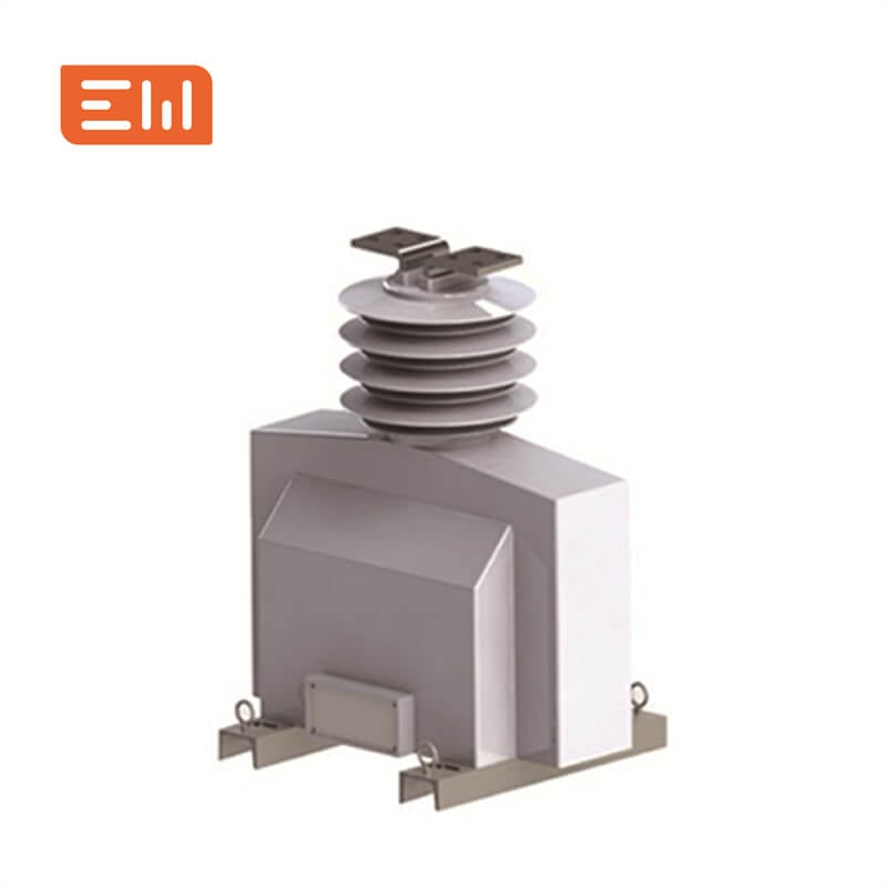
Core-Balance CTs on VFD Motor Feeders: Installation Checks Quick Answer: A core-balance CT on a VFD feeder must be installed around the intended conductors and coordinated with the drive's leakage-current behavior, cable shielding, and earth-fault ...
VIEW MORE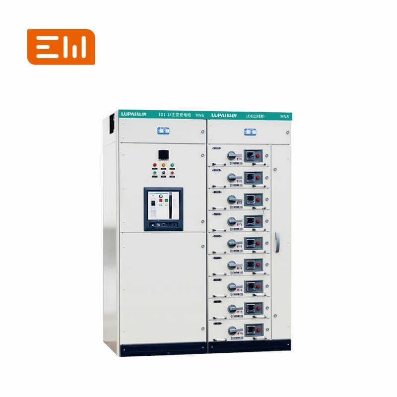
LV Switchboard Spare Feeders vs. Spare Capacity: RFQ Checklist Quick Answer: An unused feeder space is not automatically spare electrical capacity. Future expansion depends on busbar rating, thermal verification, fault level, cable entry, protectio...
VIEW MORE
DOL vs. Star-Delta vs. Soft Starter vs. VFD in an MCC Quick Answer: Motor-starting method selection balances starting current, torque, start time, process control, power quality, and maintenance. DOL, star-delta, soft starter, and VFD schemes are n...
VIEW MORE
Neutral Protection on 4-Pole ACBs: Sensing and Trip Settings Quick Answer: A four-pole ACB can switch the neutral, but neutral overcurrent protection depends on the breaker trip unit, sensor arrangement, and system design. Verify what is measured, ...
VIEW MORE
Icu vs. Ics for LV Circuit Breakers: Ultimate and Service Capacity Quick Answer: Icu and Ics are different short-circuit breaking-capacity ratings for a low-voltage circuit-breaker. Selection must compare the prospective fault current at the instal...
VIEW MORE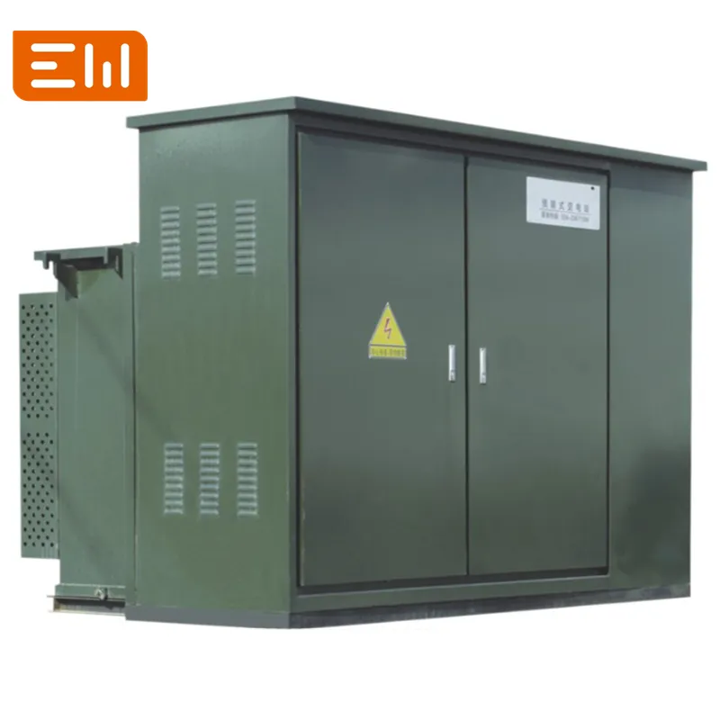
Transformer-to-LV Panel Links in Compact Substations: Cable or Busbar Quick Answer: The transformer-to-LV-panel link in a compact substation can use cables or a busbar connection, depending on current, route geometry, enclosure layout, fault duty, ...
VIEW MORE
Prefabricated Substation Temperature and Site-Rating Guide Quick Answer: Site temperature, solar gain, and altitude can change a prefabricated substation's usable rating. Assess ambient conditions, internal ventilation, transformer loading, and MV/...
VIEW MORE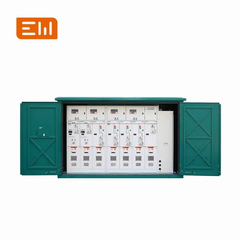
RMU Cable-Screen Earthing and Bonding at MV Terminations Quick Answer: Cable-screen earthing at an RMU termination must follow the cable construction, gland or connector design, fault-current path, and the project's single-line and earthing scheme....
VIEW MORE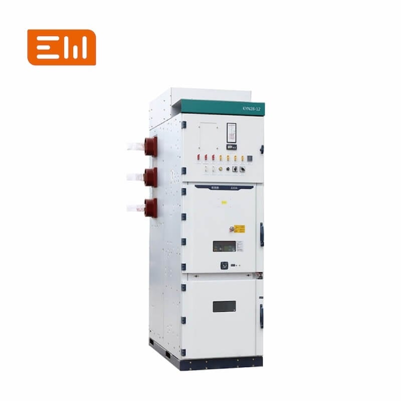
Earthing-Switch Making Current vs. Short-Time Withstand Quick Answer: Short-time withstand and short-circuit making capability describe different duties for an earthing switch. One concerns carrying fault current for a specified duration; the other...
VIEW MORE
LSC Categories in MV Switchgear: Service-Continuity Planning Quick Answer: Loss-of-service-continuity categories describe how far an MV switchgear assembly can remain energized when an accessible compartment is opened, under the defined design and ...
VIEW MORE
RMU VPIS vs. VDS: Voltage Presence and Phase Comparison Quick Answer: A voltage presence indicating system provides a visual indication related to energized conductors, while a voltage detecting system or approved interface may support additional t...
VIEW MORE
3-Pole vs. 4-Pole ACB: Neutral Switching and System Earthing Quick Answer: The choice between a three-pole and four-pole ACB depends on the earthing system, source-transfer arrangement, neutral current, and whether the neutral must be switched. A f...
VIEW MORE
Rated Diversity Factor in LV Assemblies: What the Schedule Must State Quick Answer: Rated diversity factor describes the assumed simultaneous loading of outgoing circuits in an assembly under defined conditions. It affects thermal design and should...
VIEW MORE
MCC Motor Starting Current and Voltage-Dip Review Quick Answer: Motor starting affects feeder current, bus voltage, protection coordination, and the operation of neighboring loads. An MCC design should use the motor starting method, source impedanc...
VIEW MORE
Type 1 vs. Type 2 Coordination for MCC Motor Starters Quick Answer: Type 1 and Type 2 coordination describe different post-short-circuit conditions for a motor-starter combination. The specified breaker or fuse, contactor, overload relay, and motor...
VIEW MORE
ACB Trip-Circuit Supervision: Wiring, Alarm, and Test Points Quick Answer: Trip-circuit supervision monitors selected parts of the breaker trip path so an open wire, failed supply, or coil issue can be alarmed before a protection demand. The scheme...
VIEW MORE
ACB Shunt Trip vs. Undervoltage Release: Control-Scheme Choice Quick Answer: A shunt trip opens an ACB when its trip coil receives a control signal; an undervoltage release opens or prevents closing when its supply falls below the device's specifie...
VIEW MORE
Protective-Earth Bonding and Continuity in LV Switchboards Quick Answer: Protective-earth continuity in a switchboard depends on a deliberate low-impedance bonding path between the enclosure, doors, gland plates, cable screens where specified, and ...
VIEW MORE
LV Switchboard Neutral Sizing for Unbalanced and Harmonic Loads Quick Answer: Neutral-conductor sizing in a low-voltage switchboard depends on system arrangement, load imbalance, triplen harmonics, protective-device behavior, and the assembly manuf...
VIEW MORE
VT Fuse-Failure Supervision: Distinguishing Loss of Voltage Quick Answer: VT fuse-failure supervision helps a protection or control system distinguish loss of a VT secondary signal from a genuine system voltage condition. The logic should match the...
VIEW MORE
VT Polarity and Phase-Sequence Checks During Commissioning Quick Answer: VT polarity and phase-sequence checks confirm that secondary voltages correspond to the intended primary phases and reference direction. They should be completed before enabli...
VIEW MORE
VT Secondary Voltage Drop: Cable Sizing for Metering and Relays Quick Answer: VT secondary cable resistance can create a voltage error at a distant meter or relay. Estimate the complete loop drop using winding burden, cable length, conductor size, ...
VIEW MORE
VT Voltage Factor Selection for Ground-Fault Conditions Quick Answer: A voltage factor describes a VT's ability to withstand an elevated primary voltage for a stated duration under defined system conditions. Selection must match the grounding metho...
VIEW MORE
CT Selection for Restricted Earth-Fault Protection Quick Answer: Restricted earth-fault protection depends on a coordinated set of phase and neutral CTs, matching polarity and ratio references, a defined protected zone, and a compatible relay. CT s...
VIEW MORE
CT Secondary Grounding and Test-Switch Arrangement Quick Answer: A CT secondary circuit needs an intentional grounding arrangement and safe test access defined by the protection design. Grounding points, shorting links, and test-switch contacts mus...
VIEW MORE
CT Polarity and S1/S2 Terminal Verification Before Wiring Quick Answer: CT polarity verification confirms the relationship between primary and secondary reference directions so metering, differential, and earth-fault circuits sum correctly. Termina...
VIEW MORE
CT Primary Injection vs. Secondary Injection: Test Scope Quick Answer: Primary injection drives current through the CT primary path and can verify more of the installed chain. Secondary injection tests the relay or meter input circuit from the CT s...
VIEW MORE
Core-Balance CT vs. Three-CT Residual Connection Quick Answer: A core-balance CT surrounds the complete set of live conductors, while a residual connection sums the secondary outputs of phase CTs. The choice depends on feeder layout, protection sen...
VIEW MORE
Core-Balance CT Selection for Sensitive Earth-Fault Protection Quick Answer: A core-balance current transformer measures the vector sum of conductors passing through its aperture. Selection starts with the complete conductor set, maximum load curre...
VIEW MORE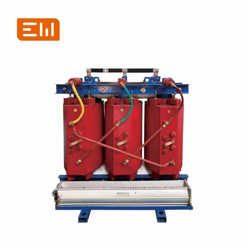
Dry-Type Transformer Insulation Resistance and PI Testing Quick Answer: Insulation-resistance and polarization-index readings on a dry-type transformer are meaningful only when winding connections, temperature, humidity, test voltage, and timing ar...
VIEW MORE
OLTC Dynamic Resistance Measurement: What the Trace Can Show Quick Answer: Dynamic resistance measurement records resistance behavior while an on-load tap changer operates under a specified test setup. The trace can reveal transition behavior or co...
VIEW MORE
Transformer Bushing Capacitance and Power-Factor Test Guide Quick Answer: A capacitance and power-factor test on a condenser bushing checks a defined insulation system through its test tap. Test mode, voltage, tap condition, temperature, and bushin...
VIEW MORE
Applied vs. Induced Voltage Tests for Transformer Insulation Quick Answer: Applied-voltage and induced-voltage tests stress different insulation relationships in a transformer. The approved test schedule identifies which windings are energized, how...
VIEW MORE
Transformer Core-Ground Insulation Test and Multiple Grounds Quick Answer: A core-ground check verifies that a transformer core has the intended single grounding point and that unintended conductive paths are not masking a second ground. The exact ...
VIEW MORE
Transformer Excitation-Current Test: Phase Pattern and Context Quick Answer: An excitation-current test records the current drawn by a winding under a specified test voltage and connection. Phase pattern and comparison data may help investigate cor...
VIEW MORE
Transformer Insulation Power-Factor and Tan-Delta Testing Quick Answer: Power-factor or tan-delta testing evaluates dielectric losses in an insulation system under a defined test connection. Results depend on temperature, test voltage, guarding, co...
VIEW MORE
Transformer SFRA: Baselines, Fingerprints, and Transport Checks Quick Answer: Sweep frequency response analysis (SFRA) compares a transformer's electrical response over a frequency range with a valid reference trace. It is most useful when test con...
VIEW MORE
Transformer Winding Resistance Test: Phase and Tap Comparison Quick Answer: A winding-resistance test measures the DC resistance of accessible windings and connections. Phase-to-phase and tap-to-tap comparisons can reveal connection or contact issu...
VIEW MORE
Transformer Turns Ratio Test: Tap Position and Vector Group Checks Quick Answer: A transformer turns-ratio test checks whether measured winding ratios match the specified voltage ratio at the selected tap. It should be read with connection and phas...
VIEW MORE
Open-Delta VT Residual Voltage for Earth-Fault Detection Quick Answer: An open-delta connection of VT secondary windings provides residual voltage for earth-fault detection, but its expected output depends on system grounding, VT ratio, winding ar...
VIEW MORE
Skid-Mounted Substation Specification Guide Quick Answer: A skid-mounted substation assembles transformer and switching equipment on a transportable structural base, reducing field assembly while requiring careful coordination of lifting, vibratio...
VIEW MORE
Containerized Substation for Data Center Power Deployment Quick Answer: A containerized substation packages power equipment in a factory-integrated enclosure to shorten site work, but availability depends on the internal one-line, redundancy, ther...
VIEW MORE
RMU Cable Testing Access, Test Bushings, and Safe Isolation Quick Answer: RMU cable testing must isolate the cable from energized buswork and sensitive equipment, establish safe earthing and discharge steps, and provide a manufacturer-approved con...
VIEW MORE
Motorized RMU Operating Mechanism for SCADA and Automation Quick Answer: A motorized RMU adds an actuator and control interface so load-break switches or breakers can be operated remotely, but safe automation also requires reliable position feedba...
VIEW MORE
Extensible vs Non-Extensible RMU: Expansion Planning Guide Quick Answer: An extensible RMU provides a designed bus interface for adding compatible modules, while a non-extensible unit is a fixed assembly that is often simpler when the final feeder...
VIEW MORE
Automatic Recloser vs Outdoor Vacuum Circuit Breaker Quick Answer: An automatic recloser combines interruption, protection control, and programmed reclosing for distribution feeders, while an outdoor VCB may rely more heavily on an external relay,...
VIEW MORE
Withdrawable VCB Racking Mechanism and Interlock Checklist Quick Answer: A withdrawable VCB mechanism moves the breaker between service, test, and disconnected positions while interlocks prevent unsafe movement, closing, door opening, and earthing...
VIEW MORE
Vacuum Circuit Breaker Timing and Contact Resistance Tests Quick Answer: VCB timing and contact-resistance tests help identify mechanism, alignment, and current-path problems, but results must be compared with manufacturer limits and the breaker's...
VIEW MORE
Detuned Reactor Capacitor Bank Selection for LV Networks Quick Answer: A detuned reactor is connected in series with capacitor steps to shift resonance and reduce harmonic stress, but the reactor and capacitor must be selected as a coordinated sys...
VIEW MORE
LV Switchboard Icw and Ipk Short-Circuit Ratings Explained Quick Answer: Icw describes short-time withstand current for a stated duration, while Ipk describes peak withstand current; both must be coordinated with the prospective fault current and ...
VIEW MORE
IEC 61439 Form of Separation for LV Switchgear Explained Quick Answer: Form of separation describes internal partitioning between busbars, functional units, and external conductor terminals; a higher form can improve access segregation but also in...
VIEW MORE
Active Harmonic Filter Panel Selection for Nonlinear Loads Quick Answer: An active harmonic filter measures distorted load current and injects compensating current, but its rating and effectiveness depend on the harmonic spectrum, CT placement, ne...
VIEW MORE
Automatic Transfer Switch Panel: Utility and Generator Guide Quick Answer: An ATS panel monitors normal and standby sources and transfers selected loads according to a defined sequence; reliable operation depends on source compatibility, transitio...
VIEW MORE
Switchgear Spare Parts List for Overseas and Remote Projects Quick Answer: A useful switchgear spare-parts list is based on installed quantities, failure consequence, replacement lead time, commonality, shelf life, commissioning needs, and local m...
VIEW MORE
Switchgear Shipping Sections and Site Busbar Reassembly Checklist Quick Answer: Long switchgear lineups are often divided into shipping sections, which makes transport practical but transfers critical busbar, enclosure, wiring, and alignment work ...
VIEW MORE
24kV Metal-Clad Switchgear Procurement Guide Quick Answer: A 24kV switchgear inquiry should define the highest system voltage, insulation level, normal current, short-circuit duty, panel functions, breaker arrangement, protection, metering, cable ...
VIEW MORE
Top vs Bottom Cable Entry in MV and LV Switchgear Quick Answer: Cable-entry direction changes cabinet layout, civil works, bending space, termination access, gland-plate design, segregation, and installation sequence, so it must be fixed before pa...
VIEW MORE
Switchgear Auxiliary Control Power: AC vs DC Supply Selection Quick Answer: Switchgear control power supplies breaker trip and close coils, protection relays, motors, indications, communications, and heaters; DC is common where tripping must remai...
VIEW MORE
MV Switchgear Bus Coupler Panel: Selection and Operating Logic Quick Answer: An MV bus coupler connects two bus sections so loads can transfer or share sources, but closing permission must be governed by source compatibility, fault level, interloc...
VIEW MORE
ENWEI Electric - China’s professional switchgear & transformer manufacturer since 2000. Specializing in high/low voltage switchgear, power & current transformers.
No. 6688, Building 1, Xuyang Road, Headquarters Economic Park, Yueqing City, Wenzhou City, Zhejiang Province, China
Copyright © Wenzhou Enwei Intelligent Equipment Co., Ltd. All Rights Reserved | Privacy Policy | Blog
 EN