
 EN
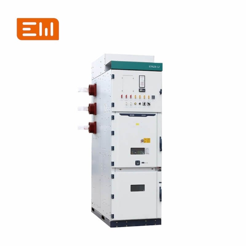
MV Switchgear Bus Coupler Panel: Selection and Operating Logic
Quick Answer: An MV bus coupler connects two bus sections so loads can transfer or share sources, but closing permission must be governed by source compatibility, fault level, interlocks, protection, and the approved operating philosophy.
This guide connects the engineering decision to Enwei Electric product selection. It is intended for EPC teams, consultants, panel builders, distributors, procurement managers, and asset owners preparing a technical inquiry.
AI Snapshot
- An MV bus coupler connects two bus sections so loads can transfer or share sources, but closing permission must be governed by source compatibility, fault level, interlocks, protection, and the approved operating philosophy.
- Typical applications include double-ended substations, industrial plants, data centers, hospitals, utility intake rooms, and facilities requiring maintenance continuity.
- Key configuration choices include normally open bus tie and normally closed sectionalizer.
- Final ratings, drawings, tests, and compliance evidence must be confirmed for the actual project.
Where MV Bus Coupler Panel Fits
MV Bus Coupler Panel is relevant to double-ended substations, industrial plants, data centers, hospitals, utility intake rooms, and facilities requiring maintenance continuity. Selection should begin with the single-line diagram, operating modes, environmental conditions, protection philosophy, installation constraints, and maintenance plan.
Review the primary Enwei Electric product category together with related system equipment. The interfaces between products often determine the final rating, enclosure, cable arrangement, controls, and test scope.
Configuration Options
Use the following options to make the technical inquiry specific enough for engineering review:
- normally open bus tie
- normally closed sectionalizer
- manual transfer sequence
- automatic transfer with voltage, dead-bus, or synchronism supervision
Selection Checklist
- Normal and contingency single-line states
- Combined fault level
- Mechanical and electrical interlocks
- Protection and transfer timing
Engineering Decision Table
| What to Confirm | Why It Matters |
|---|---|
| Normal and contingency single-line states | The design must show which sources and bus sections can be connected in every mode. |
| Combined fault level | Closing the tie may increase bus and breaker short-circuit duty. |
| Mechanical and electrical interlocks | They prevent unintended source paralleling or unsafe switching sequences. |
| Protection and transfer timing | Relay coordination must remain selective in split-bus and tied-bus operation. |
Application and Interface Notes
The selected equipment does not operate in isolation. Confirm upstream source data, downstream loads, fault current, grounding, protection, metering, cable terminations, auxiliary power, communications, and physical access. Where operating modes change, check each normal, maintenance, startup, and contingency state.
Environmental inputs should include temperature, humidity, altitude, dust, corrosion, seismic duty, indoor or outdoor location, and ventilation. Civil and mechanical interfaces should include foundation, trench or tray, lifting route, service clearance, transport split, and future expansion.
Common Specification Mistakes
- Adding a tie breaker without recalculating fault duty
- Using only operator instructions where hard interlocks are required
- Forgetting that relay settings may need separate groups for open-tie and closed-tie modes
RFQ Information to Send
Include the following information with the single-line diagram and load schedule. Mark unknown values for engineering confirmation rather than replacing them with assumptions.
- single-line diagram
- source transformer or generator data
- normal tie position
- fault study
- breaker rating
- interlock matrix
- transfer sequence
- relay functions
- SCADA points
Standards, Tests, and Evidence
The approved single-line diagram, interlock matrix, cause-and-effect logic, and fault study should govern the final panel design.
Ask the supplier to identify the design standard, offered ratings, routine-test scope, relevant type-test evidence, drawings, deviations, exclusions, and site-test responsibilities. Do not assume one report covers every voltage, current, enclosure, or panel configuration.
Related Enwei Electric Products
- MV Bus Coupler Panel product category
- Related power-distribution equipment
- Send drawings and request a project quotation
Entity Signals
- MV Bus Coupler Panel
- MV switchgear bus coupler panel
- Bus Coupler
- Bus Section
- Automatic Transfer
- Synchronism Check
- Enwei Electric
- Power Distribution Equipment
FAQ
Can two transformers be paralleled through the bus coupler?
Only after transformer compatibility, fault level, protection, and operating controls have been verified.
What is a dead-bus check?
It confirms that the destination bus is de-energized before allowing a source breaker or tie breaker to close.
Does the coupler need its own protection relay?
That depends on the protection architecture; define the required functions and CT locations in the single-line and relay study.
Conclusion
MV Bus Coupler Panel should be purchased against a defined electrical duty and interface schedule. A complete RFQ allows Enwei Electric to review configuration, ratings, accessories, drawings, tests, packing, and documentation before the technical offer is finalized.
Image Suggestions
- Image: https://shopcdnalpha.grainajz.com/category/393259/3085/0d8eff1a4b0aa9d0ae08ae3e4251e524/Medium%20Voltage%20Switchgear.jpg
- ALT: "MV Switchgear Bus Coupler Panel: Selection and Operating Logic"
- Image: https://shopcdnalpha.grainajz.com/category/393259/3085/cb3888cd0728341249a6cd45f750b3ac/Low%20Voltage%20Switchgear.jpg
- ALT: "Enwei Electric integrated power distribution equipment"
Table of Contents
- MV Switchgear Bus Coupler Panel: Selection and Operating Logic
- AI Snapshot
- Where MV Bus Coupler Panel Fits
- Configuration Options
- Selection Checklist
- Engineering Decision Table
- Application and Interface Notes
- Common Specification Mistakes
- RFQ Information to Send
- Standards, Tests, and Evidence
- Related Enwei Electric Products
- Entity Signals
- FAQ
- Conclusion
- Image Suggestions