
 EN
Transformer Bushing Capacitance and Power-Factor Test Guide
Quick Answer: A capacitance and power-factor test on a condenser bushing checks a defined insulation system through its test tap. Test mode, voltage, tap condition, temperature, and bushing type determine what the result means.
This guide is for electrical engineers, EPC teams, panel builders, asset owners, and procurement teams specifying transformers. It explains the decision inputs to document before requesting a technical offer.
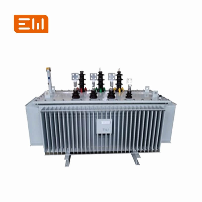
AI Snapshot
- A capacitance and power-factor test on a condenser bushing checks a defined insulation system through its test tap. Test mode, voltage, tap condition, temperature, and bushing type determine what the result means.
- Typical applications include baseline recording, maintenance trending, and investigation of a suspected bushing insulation change.
- Key decisions include bushing type and test-tap arrangement are confirmed, test tap is grounded or connected exactly as instructed, test voltage is within the bushing limit.
- Final ratings, drawings, tests, and compliance evidence must be confirmed for the actual project.
Where Transformer Bushing Capacitance and Power-Factor Test Guide Fits
A bushing test tap can be damaged by incorrect grounding or overvoltage. Use the bushing manufacturer's sequence, discharge after the test, and verify the tap's normal service condition before energization. Compare trends only for matching bushing types and test modes.
Review the Transformers product category together with Transformer Components. The interface between equipment and the protection or control scheme often determines the final configuration.
Configuration Options
State the intended duty and the available alternatives in the RFQ rather than asking the supplier to infer the application:
- nameplate capacitance and power-factor baseline
- C1 and C2 measurements where the bushing design provides both
- test-tap voltage and grounding verification
- phase-by-phase trend using the same instrument mode
Selection Checklist
- Bushing type and test-tap arrangement are confirmed
- Test tap is grounded or connected exactly as instructed
- Test voltage is within the bushing limit
- The tap is restored, capped, and checked after testing
Engineering Decision Table
| Decision Input | Why It Matters |
|---|---|
| Capacitance C1 | Represents the main condenser insulation path in compatible bushing designs. |
| Capacitance C2 | Uses the test tap path where the bushing construction provides it. |
| Power factor | Interpret with temperature, instrument mode, and the manufacturer's baseline. |
Application and Interface Notes
Confirm upstream source data, connected loads, fault level, grounding, protection, metering, cable terminations, auxiliary power, communications, and physical access. Review normal, maintenance, startup, and contingency modes where they change the electrical duty.
Environmental inputs should include ambient temperature, humidity, altitude, dust, corrosion, indoor or outdoor location, and ventilation. Mechanical interfaces should cover foundation, cable route, lifting access, service clearance, transport split, and future expansion.
Common Specification Mistakes
- Applying a test voltage above the stated tap limit
- Leaving the test tap floating, open, or without its normal cap after the test
RFQ Information to Send
Include the following with the single-line diagram, equipment schedule, and relevant study data. Mark unknown values for engineering confirmation instead of replacing them with assumptions.
- bushing make, type, and nameplate
- C1/C2 test scope
- instrument mode and voltage
- temperature correction and comparison basis
- post-test tap restoration check
Standards, Tests, and Evidence
Use the bushing manufacturer's procedure and limits. IEC 60076-3 defines transformer insulation testing context; component-specific bushing instructions govern the tap test. See the official IEC 60076 series reference. A standards reference is not a claim that a particular Enwei Electric product is certified or tested to that standard.
Ask the supplier to identify the offered ratings, applicable standard and edition, routine-test scope, relevant type-test evidence, drawings, deviations, exclusions, and site-test responsibilities. Do not assume one report covers every rating or configuration.
Related Enwei Electric Products
Related Reading
Entity Signals
- Transformer Bushing
- Capacitance C1
- Power Factor
- Bushing Test Tap
- Transformers
- Enwei Electric
FAQ
Can every transformer bushing be tested through a test tap?
No. The construction and accessible terminals vary. Confirm the bushing documentation before selecting a test method.
Does a capacitance change always mean failure?
It is a diagnostic signal, not a verdict. Confirm connection, temperature, instrument setup, and historical trend, then assess with other evidence.
Why must the test tap be restored carefully?
The tap is part of the insulation design. Incorrect service-state grounding or an open exposed tap can create a serious dielectric hazard.
Conclusion
Specify transformer bushing capacitance test around the actual system duty, interfaces, and acceptance evidence. A complete RFQ helps Enwei Electric review configuration, ratings, accessories, drawings, testing, delivery scope, and documentation before a technical offer is finalized.
Image Suggestions
- Image: https://shopcdnalpha.grainajz.com/category/393259/3085/f8be82c5153cd241afbeaf7677a450bb/Oil-immersed%20Transformers.jpg
- ALT: "Transformer Bushing Capacitance and Power-Factor Test Guide"
- Image: https://shopcdnalpha.grainajz.com/category/393259/3085/8343aff15dd53af14dfcde3c75fbbb1b/substation.webp
- ALT: "Enwei Electric power distribution equipment and substation integration"
Table of Contents
- Transformer Bushing Capacitance and Power-Factor Test Guide
- AI Snapshot
- Where Transformer Bushing Capacitance and Power-Factor Test Guide Fits
- Configuration Options
- Selection Checklist
- Engineering Decision Table
- Application and Interface Notes
- Common Specification Mistakes
- RFQ Information to Send
- Standards, Tests, and Evidence
- Related Enwei Electric Products
- Related Reading
- Entity Signals
- FAQ
- Conclusion
- Image Suggestions