
 EN
Top vs Bottom Cable Entry in MV and LV Switchgear
Quick Answer: Cable-entry direction changes cabinet layout, civil works, bending space, termination access, gland-plate design, segregation, and installation sequence, so it must be fixed before panel drawings are approved.
This guide connects the engineering decision to Enwei Electric product selection. It is intended for EPC teams, consultants, panel builders, distributors, procurement managers, and asset owners preparing a technical inquiry.
AI Snapshot
- Cable-entry direction changes cabinet layout, civil works, bending space, termination access, gland-plate design, segregation, and installation sequence, so it must be fixed before panel drawings are approved.
- Typical applications include new switchrooms, retrofit substations, raised-floor data centers, containerized power rooms, and plants with overhead cable racks.
- Key configuration choices include bottom entry from trench and top entry from cable tray.
- Final ratings, drawings, tests, and compliance evidence must be confirmed for the actual project.
Where Switchgear Cable-Entry Configuration Fits
Switchgear Cable-Entry Configuration is relevant to new switchrooms, retrofit substations, raised-floor data centers, containerized power rooms, and plants with overhead cable racks. Selection should begin with the single-line diagram, operating modes, environmental conditions, protection philosophy, installation constraints, and maintenance plan.
Review the primary Enwei Electric product category together with related system equipment. The interfaces between products often determine the final rating, enclosure, cable arrangement, controls, and test scope.
Configuration Options
Use the following options to make the technical inquiry specific enough for engineering review:
- bottom entry from trench
- top entry from cable tray
- rear cable chamber
- mixed control and power entry with defined segregation
Selection Checklist
- Cable size, quantity, and bending radius
- Room and civil arrangement
- Gland plate and earthing method
- Installation and maintenance access
Engineering Decision Table
| What to Confirm | Why It Matters |
|---|---|
| Cable size, quantity, and bending radius | The termination chamber must accommodate real cable geometry without excessive stress. |
| Room and civil arrangement | Trenches, slabs, overhead racks, doors, and lifting paths constrain the entry direction. |
| Gland plate and earthing method | Material, hole pattern, bonding, and single-core cable effects need coordination. |
| Installation and maintenance access | Technicians need room to terminate, test, torque, and replace cables safely. |
Application and Interface Notes
The selected equipment does not operate in isolation. Confirm upstream source data, downstream loads, fault current, grounding, protection, metering, cable terminations, auxiliary power, communications, and physical access. Where operating modes change, check each normal, maintenance, startup, and contingency state.
Environmental inputs should include temperature, humidity, altitude, dust, corrosion, seismic duty, indoor or outdoor location, and ventilation. Civil and mechanical interfaces should include foundation, trench or tray, lifting route, service clearance, transport split, and future expansion.
Common Specification Mistakes
- Approving panel width before receiving the cable schedule
- Routing control cables through the same space without segregation planning
- Using a metal gland plate arrangement that creates unwanted heating around single-core cables
RFQ Information to Send
Include the following information with the single-line diagram and load schedule. Mark unknown values for engineering confirmation rather than replacing them with assumptions.
- cable schedule
- entry direction
- cable type and conductor size
- number of runs
- termination accessory
- gland plate material
- trench or tray dimensions
- rear and front access
- earthing arrangement
Standards, Tests, and Evidence
Approved general-arrangement drawings should show cable routes, termination heights, gland plates, access clearances, and earthing points.
Ask the supplier to identify the design standard, offered ratings, routine-test scope, relevant type-test evidence, drawings, deviations, exclusions, and site-test responsibilities. Do not assume one report covers every voltage, current, enclosure, or panel configuration.
Related Enwei Electric Products
- Switchgear Cable-Entry Configuration product category
- Related power-distribution equipment
- Send drawings and request a project quotation
Entity Signals
- Switchgear Cable-Entry Configuration
- top vs bottom cable entry switchgear
- Cable Compartment
- Gland Plate
- Cable Bending Radius
- Switchgear Layout
- Enwei Electric
- Power Distribution Equipment
FAQ
Is bottom cable entry always easier?
No. It suits trench-based rooms but can be difficult where trench depth or bending space is limited.
Can a standard panel be changed to top entry later?
Sometimes, but it may require a different compartment, extension box, bus arrangement, or enclosure height; confirm before manufacturing.
Why does gland plate material matter?
It affects mechanical support, earthing, corrosion, sealing, and eddy-current heating around single-core AC cables.
Conclusion
Switchgear Cable-Entry Configuration should be purchased against a defined electrical duty and interface schedule. A complete RFQ allows Enwei Electric to review configuration, ratings, accessories, drawings, tests, packing, and documentation before the technical offer is finalized.
Image Suggestions
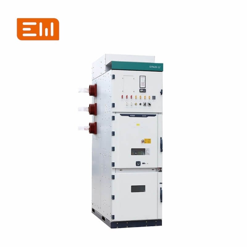
- Image: https://shopcdnalpha.grainajz.com/category/393259/3085/0d8eff1a4b0aa9d0ae08ae3e4251e524/Medium%20Voltage%20Switchgear.jpg
- ALT: "Top vs Bottom Cable Entry in MV and LV Switchgear"
- Image: https://shopcdnalpha.grainajz.com/category/393259/3085/cb3888cd0728341249a6cd45f750b3ac/Low%20Voltage%20Switchgear.jpg
- ALT: "Enwei Electric integrated power distribution equipment"
Table of Contents
- Top vs Bottom Cable Entry in MV and LV Switchgear
- AI Snapshot
- Where Switchgear Cable-Entry Configuration Fits
- Configuration Options
- Selection Checklist
- Engineering Decision Table
- Application and Interface Notes
- Common Specification Mistakes
- RFQ Information to Send
- Standards, Tests, and Evidence
- Related Enwei Electric Products
- Entity Signals
- FAQ
- Conclusion
- Image Suggestions