
 EN
Transformer Inrush Current and Protection Coordination Guide
Quick Answer: Magnetizing inrush is a temporary current produced when a transformer is energized, and protection must distinguish it from internal faults without sacrificing genuine fault sensitivity.
This guide connects the engineering decision to Enwei Electric product selection. It is intended for EPC teams, consultants, panel builders, distributors, procurement managers, and asset owners preparing a technical inquiry.
AI Snapshot
- Magnetizing inrush is a temporary current produced when a transformer is energized, and protection must distinguish it from internal faults without sacrificing genuine fault sensitivity.
- Typical applications include distribution substations, factory transformers, renewable step-up units, data centers, and networks with repeated automatic transfer operations.
- Key configuration choices include differential protection with harmonic restraint or blocking and time-overcurrent coordination.
- Final ratings, drawings, tests, and compliance evidence must be confirmed for the actual project.
Where Transformer Protection Package Fits
Transformer Protection Package is relevant to distribution substations, factory transformers, renewable step-up units, data centers, and networks with repeated automatic transfer operations. Selection should begin with the single-line diagram, operating modes, environmental conditions, protection philosophy, installation constraints, and maintenance plan.
Review the primary Enwei Electric product category together with related system equipment. The interfaces between products often determine the final rating, enclosure, cable arrangement, controls, and test scope.
Configuration Options
Use the following options to make the technical inquiry specific enough for engineering review:
- differential protection with harmonic restraint or blocking
- time-overcurrent coordination
- fuse-based transformer feeder protection
- controlled switching where project economics justify it
Selection Checklist
- Transformer size and core design
- Source impedance and point-on-wave closing
- Residual flux and energization sequence
- Relay, fuse, CT, and breaker characteristics
Engineering Decision Table
| What to Confirm | Why It Matters |
|---|---|
| Transformer size and core design | These factors influence the expected energization current envelope. |
| Source impedance and point-on-wave closing | Network strength and switching instant affect peak current. |
| Residual flux and energization sequence | A recently de-energized core may produce a different inrush event. |
| Relay, fuse, CT, and breaker characteristics | The complete protection chain must ride through inrush and clear faults. |
Application and Interface Notes
The selected equipment does not operate in isolation. Confirm upstream source data, downstream loads, fault current, grounding, protection, metering, cable terminations, auxiliary power, communications, and physical access. Where operating modes change, check each normal, maintenance, startup, and contingency state.
Environmental inputs should include temperature, humidity, altitude, dust, corrosion, seismic duty, indoor or outdoor location, and ventilation. Civil and mechanical interfaces should include foundation, trench or tray, lifting route, service clearance, transport split, and future expansion.
Common Specification Mistakes
- Raising overcurrent settings without checking downstream fault sensitivity
- Treating all high current at energization as a transformer fault
- Ignoring CT saturation in differential protection studies
RFQ Information to Send
Include the following information with the single-line diagram and load schedule. Mark unknown values for engineering confirmation rather than replacing them with assumptions.
- transformer kVA and voltage ratio
- vector group
- impedance
- source fault level
- switching device
- CT ratios and classes
- relay model and functions
- proposed settings study
Standards, Tests, and Evidence
Protection settings must be based on the actual transformer, CT performance, relay logic, and network study; they should not be copied from another project.
Ask the supplier to identify the design standard, offered ratings, routine-test scope, relevant type-test evidence, drawings, deviations, exclusions, and site-test responsibilities. Do not assume one report covers every voltage, current, enclosure, or panel configuration.
Related Enwei Electric Products
- Transformer Protection Package product category
- Related power-distribution equipment
- Send drawings and request a project quotation
Entity Signals
- Transformer Protection Package
- transformer inrush current protection
- Magnetizing Inrush
- Transformer Differential Protection
- Overcurrent Relay
- Current Transformer
- Enwei Electric
- Power Distribution Equipment
FAQ
How long does transformer inrush last?
The high initial peak decays, but its exact duration depends on transformer and system conditions; use manufacturer and study data rather than a universal value.
Can inrush trip an upstream breaker?
Yes, if instantaneous or short-time settings are not coordinated with the energization envelope.
Does soft starting eliminate inrush?
Not for a conventional transformer by default. Controlled switching or pre-insertion methods require project-specific equipment and engineering.
Conclusion
Transformer Protection Package should be purchased against a defined electrical duty and interface schedule. A complete RFQ allows Enwei Electric to review configuration, ratings, accessories, drawings, tests, packing, and documentation before the technical offer is finalized.
Image Suggestions
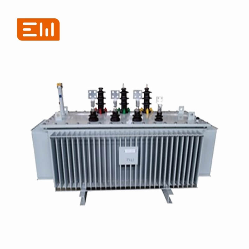
- Image: https://shopcdnalpha.grainajz.com/category/393259/3085/f8be82c5153cd241afbeaf7677a450bb/Oil-immersed%20Transformers.jpg
- ALT: "Transformer Inrush Current and Protection Coordination Guide"
- Image: https://shopcdnalpha.grainajz.com/category/393259/3085/cb3888cd0728341249a6cd45f750b3ac/Low%20Voltage%20Switchgear.jpg
- ALT: "Enwei Electric integrated power distribution equipment"
Table of Contents
- Transformer Inrush Current and Protection Coordination Guide
- AI Snapshot
- Where Transformer Protection Package Fits
- Configuration Options
- Selection Checklist
- Engineering Decision Table
- Application and Interface Notes
- Common Specification Mistakes
- RFQ Information to Send
- Standards, Tests, and Evidence
- Related Enwei Electric Products
- Entity Signals
- FAQ
- Conclusion
- Image Suggestions