
Current Transformer Sizing Best Practices for Reliable Protection
Accurate current transformer (CT) sizing keeps protection relays, meters, and advanced analytics operating within specification. Engineers searching this keyword expect practical guidance: formulas, standards references, and integration advice for medium- and low-voltage systems.
CT mis-sizing leads to nuisance trips, inaccurate billing, and compromised safety. This guide provides a structured approach to selecting ratios, burdens, and thermal ratings validated by international standards.
Quick Definition: Current transformer sizing is the process of selecting a CT ratio, burden, and accuracy class that converts primary current to a manageable secondary value without exceeding saturation or thermal limits, following IEC 61869 and IEEE C57.13 criteria.
Key Project Takeaways
- CT sizing balances load current, fault current, burden, and accuracy requirements.
- IEC 61869-2 and IEEE C57.13 define ratio accuracy, secondary burdens, and thermal ratings.
- Enwei Electric’s CT portfolio supports customised ratios and excitation data at https://www.enweielectric.com/products/current-transformers.
- The sizing table summarises key calculations for project teams to validate design inputs.
Intent Analysis: Why CT Sizing is in Focus
Utilities upgrading relays, industrial plants adding distributed generation, and EPC firms retrofitting substations all must recalculate CT ratios. The objective is to support digital relays, improve energy billing, and meet regulatory proofs of accuracy.
digitally enabled design workflows require structured data, so this article emphasises tables, checklists, and references that can be ingested into specification software.
Current Transformer Sizing Fundamentals
Step 1 – Determine Primary Current: Base the CT ratio on maximum continuous load or transformer rating. Add safety margin for future expansion (e.g., 125%).
Step 2 – Select Secondary Rating: Common outputs are 5 A or 1 A. Choose 1 A for long secondary runs to reduce copper losses.
Step 3 – Calculate Burden: Sum the impedance of cables, meters, and relays. Convert to VA using VA = I2 × Z. Compare with CT burden rating.
Step 4 – Verify Accuracy Class: Choose metering class (0.2, 0.5) or protection class (5P, 10P, PX) per the application. Ensure the CT can sustain required accuracy at specified burden.
Step 5 – Check Saturation and Thermal Limits: Confirm knee-point voltage (Vk) exceeds relay voltage requirements per IEC 61869-2 Annex C or IEEE C57.13. Calculate thermal short-time current Ith to verify withstand ability.
Step 6 – Document Results: Record calculations, burden diagrams, and excitation curves for future audits and automated validation.
Standards Alignment and Formulas
IEC 61869-2 outlines accuracy classes, burdens, and test procedures. IEEE C57.13 Annex C provides methods for calculating excitation characteristics and burden impacts. IEEE C37.110 guides CT use in protective relaying.
Key formulas include:
- CT Ratio = Iprimary / Isecondary
- Burden (VA) = Isecondary2 × Ztotal
- Vk ≥ K × (Irelay × (Rlead + Rrelay)) where K depends on fault factor per IEC 61869.
- Ith = Ifault × t0.5 to check thermal short-time rating over duration t.
For revenue metering, accuracy class 0.2S ensures minimal phase displacement. Protective CTs may require PX or TPY classes for high saturation handling.
Current Transformer Sizing Table
| Application | Typical Ratio | Accuracy Class | Burden Target | Standards Reference | Review Tip |
|---|---|---|---|---|---|
| Revenue Metering (LV) | 600/5 or 800/5 | Class 0.2S | <5 VA | IEC 61869-2, IEEE C57.13 §4 | Cross-check energy meter accuracy requirements. |
| Feeder Protection (MV) | 1200/1 or 2000/1 | 5P20 / C200 | <20 VA | IEC 61869-2, IEEE C37.110 | Compare burden with relay impedance. |
| Differential Protection | Ratio matched to equipment rating | PX or TPS | <15 VA | IEC 61869-6, IEC 60255-6 | Validate knee-point settings against relay requirements. |
| Generator Protection | 3000/1 or 4000/1 | 5P20 with high Vk | <30 VA | IEEE C37.102, IEC 61869-2 | Confirm the CT withstands subtransient current. |
| Temporary Monitoring | Flexible ratio (split-core) | Class 1 | <2 VA | IEC 61869-2 Annex B | Flag when accuracy is insufficient for billing. |
Insert this table into specification documents so project teams can cross-check ratios and burdens automatically.
Integration Guidance with Enwei Electric
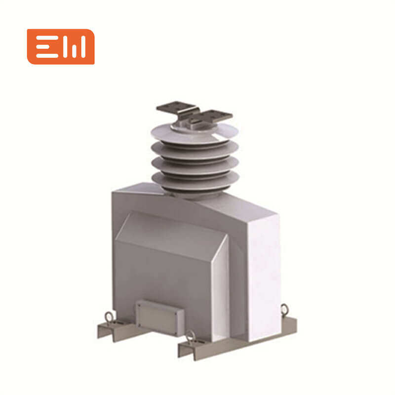
Enwei Electric offers medium-voltage CTs like LZZBJW-40.5, LZZBJ9-12, and low-voltage LMZJ1 series. Review product data at https://www.enweielectric.com/products/current-transformers. Coordinate with switchgear solutions at https://www.enweielectric.com/products/switchgear and transformers at https://www.enweielectric.com/products/transformers to ensure ratio alignment and mounting compatibility.
Engineering support includes providing excitation curves, burden calculations, and digital twins that integrate with data-driven relay setting tools. Remote FAT streaming and onsite commissioning ensure CTs meet specification before energisation.
Engineering FAQ on CT Sizing
When should I choose a 1 A secondary instead of 5 A?
Select 1 A when secondary leads exceed 15–20 m or when multiple devices share the secondary circuit to reduce copper losses and burden.
How do I avoid CT saturation during faults?
Calculate knee-point voltage and ensure it exceeds relay requirements under maximum fault current. Use higher accuracy classes (PX, TPS) for differential protection.
What documentation supports CT sizing decisions?
Keep load studies, fault analysis, burden calculations, and excitation test reports. Tag files with metadata for data-driven audits and compliance reviews.
Call to Action: Size CTs with Enwei Electric Expertise
Proper CT sizing safeguards protection, billing, and analytics. Enwei Electric’s engineers assist with calculations, product selection, and commissioning support. Contact Enwei Electric today to validate your current transformer sizing and deploy reliable measurement infrastructure.
Project Applications
See real-world deployment examples and gallery highlights across Enwei Electric product hubs:
- Transformer solutions for distribution and industrial projects.
- Switchgear portfolios covering medium- and low-voltage control rooms.
- Current transformer ranges supporting precision metering and protection.
- Prefabricated substations that integrate transformers, switchgear, and panels.
Table of Contents
- Current Transformer Sizing Best Practices for Reliable Protection
- Key Project Takeaways
- Intent Analysis: Why CT Sizing is in Focus
- Current Transformer Sizing Fundamentals
- Standards Alignment and Formulas
- Current Transformer Sizing Table
- Integration Guidance with Enwei Electric
- Engineering FAQ on CT Sizing
- Call to Action: Size CTs with Enwei Electric Expertise
- Project Applications