 EN
EN
24kV RMU Selection Guide: How to Specify the Right RMU for Your Network
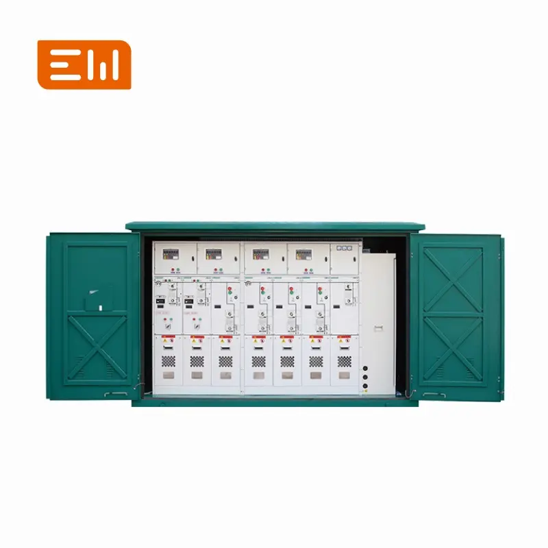
A 24kV RMU is commonly used in medium voltage distribution where cable networks and compact substations need reliable sectionalizing and transformer protection. Compared with lower voltage classes, specification gaps at 24kV can cause expensive interface rework, especially around insulation level, cable terminations, and internal arc requirements.
This guide provides a step-by-step approach to selecting the right 24kV RMU for utilities, EPCs, and industrial owners.
Step 1: Confirm the System Class and Insulation Level
Start with the system nominal voltage and applicable standards. Then confirm the required insulation levels for:
- Power frequency withstand voltage
- Lightning impulse withstand voltage (BIL)
These values are often defined by the utility or project specification. They drive clearances, insulation design, and sometimes technology selection (gas vs solid).
Step 2: Determine Fault Level (Short-Time Withstand)
Short-circuit capability is network-driven. Specify:
- Short-time withstand current (kA / duration)
- Peak withstand current
- Earthing switch making capacity (if required)
If you are unsure, request the maximum prospective short-circuit level at the RMU installation point from the utility or system study.
Step 3: Choose the Functional Units (Ways)
Most 24kV RMUs are configured as:
- Ring switches: incoming and outgoing ring ways (typically LBS).
- Transformer feeder: fused switch or circuit breaker feeder.
- Additional feeders: for branches or critical loads.
Define the single-line diagram early. It is the quickest way to prevent miscommunication about the number of ways and the protection approach.
Step 4: Select Protection Philosophy
Transformer feeder protection is usually either:
- LBS + fuse: simple and effective, common for distribution transformer protection.
- Circuit breaker + relay: preferred when coordination, automation, or higher fault duty is required.
For circuit breaker feeders, specify the relay functions (OC/EF, directional if needed) and the CT requirements (ratio, class, burden).
Step 5: Get Cable Interfaces Right
At 24kV, cable interface details matter. Include:
- Termination system: separable connectors, bushings, test points, voltage presence indicators.
- Cable size and insulation type: affects connector selection.
- Compartment layout: clearance for installation and minimum bending radius.
- Ingress protection: especially for cable compartments in outdoor kiosks.
Step 6: Define the Installation Environment
Environmental conditions influence insulation and corrosion protection. Specify:
- Indoor/outdoor: room installation vs. kiosk.
- Ambient temperature range: including solar gain for kiosks.
- Humidity/condensation risk: anti-condensation heaters or design provisions.
- Pollution severity: creepage distance requirements.
- Seismic/wind: when required by local codes.
Step 7: Automation and Monitoring Options
Modern 24kV networks often specify:
- Motorized switches: remote operation.
- Fault indicators: to reduce fault location time.
- SCADA communications: IO points, protocol requirements, control power supply.
- Metering: CT/VT module requirements if measurement is needed.
Internal Links to Support Product Navigation
Link RMU educational content to the RMU category page: Ring Main Units.
If your project shifts from compact RMUs to larger MV assemblies, link to: Switchgear.
Conclusion
A good 24kV RMU selection process starts with insulation level and fault level, then locks down functional units, protection, and cable interfaces. If you include a single-line diagram and installation constraints in your RFQ, suppliers can respond with fewer assumptions and higher accuracy.
Image Suggestions
- Image: https://www.enweielectric.com/products/rmu
- ALT: "24kV ring main unit (RMU) for medium voltage cable distribution"
- Image: https://www.enweielectric.com/products/substations
- ALT: "24kV RMU integrated in compact substation package"
Table of Contents
- 24kV RMU Selection Guide: How to Specify the Right RMU for Your Network
- Step 1: Confirm the System Class and Insulation Level
- Step 2: Determine Fault Level (Short-Time Withstand)
- Step 3: Choose the Functional Units (Ways)
- Step 4: Select Protection Philosophy
- Step 5: Get Cable Interfaces Right
- Step 6: Define the Installation Environment
- Step 7: Automation and Monitoring Options
- Internal Links to Support Product Navigation
- Conclusion
- Image Suggestions