
 EN
EN
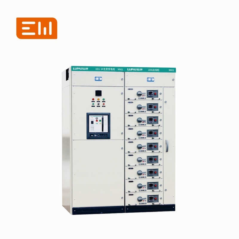
Air Circuit Breaker Diagram: A Practical Guide to ACB Structure, Wiring, and Operation
An air circuit breaker diagram shows how an Air Circuit Breaker, also called an ACB, is built and connected inside a low-voltage power distribution system. It usually includes the main power path, moving and fixed contacts, arc chute, operating mechanism, trip unit, current transformers, auxiliary contacts, and the control circuit used for closing, opening, and protection.
For engineers, panel builders, facility managers, and buyers, the diagram helps answer three practical questions:
- How does the ACB interrupt fault current?
- Where are the incoming and outgoing power connections?
- Which protection, control, and monitoring components should be selected for the application?
Basic Air Circuit Breaker Diagram
A simplified air circuit breaker diagram can be understood as two connected parts: the main circuit and the control/protection circuit.
Incoming Power
     |
     |  L1 / L2 / L3
     v
+-----------------------------+
|      Air Circuit Breaker    |
|                             |
|  Fixed Contacts             |
|       |                     |
|  Moving Contacts            |
|       |                     |
|  Arc Chute                  |
|       |                     |
|  Current Transformers       |
|       |                     |
|  Electronic Trip Unit       |
|       |                     |
|  Operating Mechanism        |
|  Closing Coil / Shunt Trip  |
|  Auxiliary Contacts         |
+-----------------------------+
     |
     |  L1 / L2 / L3
     v
Outgoing Load
In a real switchboard or distribution panel, the ACB may also include accessories such as an undervoltage release, motor charging mechanism, mechanical interlock, electrical interlock, communication module, and position indication contacts.
Main Parts Shown in an Air Circuit Breaker Diagram
1. Main Contacts
The main contacts carry the rated current during normal operation. An ACB normally uses fixed contacts and moving contacts. When the breaker is closed, current flows through these contacts. When the breaker opens, the contacts separate and an arc is created.
The quality of the contact system directly affects temperature rise, electrical life, and breaking performance.
2. Arc Chute
The arc chute is one of the most important parts in an air circuit breaker diagram. When the contacts open under load or fault conditions, an electrical arc forms between them. The arc chute divides, cools, and extinguishes the arc in air.
This is why the device is called an Air Circuit Breaker. It uses air as the arc extinguishing medium instead of vacuum, oil, or gas.
3. Operating Mechanism
The operating mechanism controls the opening and closing movement of the breaker. It may be manually operated or motorized.
Common operating components include:
- Manual charging handle
- Spring charging mechanism
- Closing button
- Opening button
- Motor charging unit
- Mechanical ON/OFF indicator
- Stored energy indicator
In draw-out type ACBs, the mechanism is also coordinated with the breaker position: connected, test, isolated, or withdrawn.
4. Electronic Trip Unit
The electronic trip unit monitors current and sends a trip command when abnormal conditions occur. It is usually connected to current transformers inside the ACB.
Typical protection functions include:
- Long-time delay protection
- Short-time delay protection
- Instantaneous protection
- Ground fault protection
- Overload protection
Advanced trip units may support LCD display, fault history, communication, energy metering, and adjustable protection settings.
5. Current Transformers
Current transformers, often shown as CTs in an air circuit breaker diagram, measure the current flowing through each phase. The trip unit uses this signal to detect overloads, short circuits, and ground faults.
Correct CT configuration is important for accurate protection performance.
6. Closing Coil
The closing coil allows the ACB to close electrically. It is commonly used in remote control systems, automatic transfer systems, and switchgear panels where operators do not close the breaker manually.
7. Shunt Trip
The shunt trip opens the breaker when it receives an electrical signal. It is often connected to emergency stop systems, fire protection systems, remote trip commands, or protection relays.
8. Undervoltage Release
An undervoltage release trips the breaker when the control voltage drops below a specified level. It prevents the breaker from remaining closed during abnormal voltage conditions.
9. Auxiliary Contacts
Auxiliary contacts provide breaker status signals to control circuits, PLCs, meters, alarm systems, and building management systems.
Common signals include:
- Breaker open
- Breaker closed
- Breaker tripped
- Spring charged
- Draw-out position status
Air Circuit Breaker Working Principle
The working principle of an air circuit breaker is based on mechanical contact separation and arc extinction in air.
When the ACB is closed, current flows through the main contacts. If the circuit operates normally, the breaker remains closed and continuously supplies power to the load.
When an overload or short circuit occurs, the trip unit detects abnormal current through the CTs. Once the measured current exceeds the protection setting, the trip unit activates the trip mechanism. The moving contacts separate from the fixed contacts, interrupting the circuit.
During this separation, an arc forms between the contacts. The arc is guided into the arc chute, where it is split into smaller arcs, cooled, and extinguished. After the arc is extinguished, the current stops flowing and the downstream equipment is protected.
Typical Air Circuit Breaker Wiring Diagram
A typical ACB wiring diagram includes both power wiring and control wiring.
Power Circuit:

Transformer / Generator
        |
        v
Main Busbar
        |
        v
Air Circuit Breaker
        |
        v
Distribution Busbar
        |
        v
Loads / MCC / Panels
Control Circuit:
Control Power
|
+---- Closing Button ---- Closing Coil
|
+---- Trip Button ------- Shunt Trip
|
+---- Protection Relay -- Trip Input
|
+---- Auxiliary Contact - Status Signal
|
+---- Motor Operator ---- Spring ChargingThe exact wiring depends on the ACB model, rated voltage, control voltage, accessories, and switchgear design. Always follow the manufacturer's wiring diagram before installation.
Common Types of Air Circuit Breaker Diagrams
Fixed Type ACB Diagram
A fixed type ACB is mounted directly inside the switchgear. The incoming and outgoing terminals are connected to the busbar or cable system. It is suitable for applications where frequent withdrawal is not required.
Fixed type ACBs are often used in compact distribution panels and cost-sensitive projects.
Draw-Out Type ACB Diagram
A draw-out type ACB includes a breaker body and a cradle. The breaker can be moved between connected, test, isolated, and withdrawn positions.
This structure improves maintenance safety and convenience. It is commonly used in main distribution boards, industrial switchgear, data centers, and large commercial power systems.
3-Pole ACB Diagram
A 3-pole ACB protects three-phase circuits without switching the neutral conductor. It is widely used in standard three-phase low-voltage distribution systems.
4-Pole ACB Diagram
A 4-pole ACB switches three phases and neutral. It is often used where neutral isolation is required, such as generator systems, transfer systems, and certain commercial or industrial installations.
Application Scenarios for Air Circuit Breakers
Air circuit breakers are mainly used in low-voltage power distribution systems where high current capacity, reliable protection, and easy maintenance are required.
Common application scenarios include:
- Main incoming breaker for low-voltage switchgear
- Transformer secondary protection
- Generator output protection
- Main distribution board protection
- Automatic transfer switch systems
- Industrial plant power distribution
- Commercial building electrical rooms
- Data center power distribution
- Motor control center incoming protection
- Marine and infrastructure electrical systems
For high-current applications, an ACB is often preferred over a molded case circuit breaker because it provides higher breaking capacity, more flexible protection settings, and better maintainability.
How to Choose an Air Circuit Breaker
When selecting an ACB, the diagram is only one part of the decision. The technical specification must match the electrical system and protection requirements.
1. Rated Current
Choose the rated current according to the load current, system design margin, and temperature conditions. Common ACB current ratings include 630A, 800A, 1000A, 1250A, 1600A, 2000A, 2500A, 3200A, 4000A, and above.
2. Rated Operating Voltage
The rated voltage must match the system voltage. Air circuit breakers are commonly used in low-voltage AC systems such as 400V, 415V, 440V, 480V, or 690V.
3. Breaking Capacity
The breaking capacity must be higher than the prospective short-circuit current at the installation point. This is one of the most important safety parameters.
Check values such as:
- Icu: ultimate short-circuit breaking capacity
- Ics: service short-circuit breaking capacity
- Icw: short-time withstand current
4. Number of Poles
Select 3P or 4P according to the system grounding method, neutral requirements, generator application, and project specification.
5. Installation Type
Choose fixed type or draw-out type based on maintenance requirements, switchgear design, space, and budget.
6. Protection Functions
Select the trip unit according to the protection needs of the system. Basic protection may be enough for simple distribution, while critical systems may require advanced protection, metering, communication, and event recording.
7. Control Voltage
Confirm the voltage for the closing coil, shunt trip, undervoltage release, and motor charging mechanism. Common control voltages include AC 110V, AC 220V, DC 110V, and DC 220V, depending on the project.
8. Accessories
Common ACB accessories include:
- Shunt trip
- Closing coil
- Undervoltage release
- Motor operator
- Auxiliary contact
- Alarm contact
- Mechanical interlock
- Electrical interlock
- Communication module
- Door interlock
- Position indication contact
9. Standards and Certification
Check whether the ACB complies with the required electrical standards for the project market. Common references include IEC standards for low-voltage circuit breakers and relevant local certification requirements.
ACB Diagram vs MCCB Diagram
An air circuit breaker diagram is usually more complex than an MCCB diagram because an ACB is designed for larger current ratings, higher breaking performance, more flexible protection settings, and more accessories.
| Item | Air Circuit Breaker | Molded Case Circuit Breaker |
|---|---|---|
| Common use | Main distribution, high-current systems | Branch circuits, smaller distribution |
| Current rating | Higher | Lower to medium |
| Protection settings | More adjustable | Basic to advanced, depending on model |
| Maintenance | Easier, especially draw-out type | Usually limited |
| Accessories | More options | Fewer options |
| Installation | Switchgear and main panels | Distribution boards and panels |
Reading an Air Circuit Breaker Diagram Step by Step
To read an air circuit breaker diagram, follow the power flow first, then check the control circuit.
- Identify the incoming power terminals.
- Follow the main current path through the contacts.
- Locate the CTs and trip unit.
- Check the arc chute and contact system.
- Identify outgoing terminals to the load.
- Review the closing coil and shunt trip circuit.
- Confirm auxiliary contact signals.
- Check control voltage and wiring labels.
- Match the accessories with the project requirements.
- Verify the diagram against the manufacturer's installation manual.
FAQ
What is an air circuit breaker diagram?
An air circuit breaker diagram is a technical drawing that shows the structure, power circuit, control circuit, and protection components of an ACB. It helps users understand how the breaker connects, operates, trips, and protects the electrical system.
What is the function of an air circuit breaker?
The main function of an air circuit breaker is to protect low-voltage electrical systems from overloads, short circuits, and ground faults. It interrupts current by opening its contacts and extinguishing the arc in air.
What are the main parts of an ACB?
The main parts of an ACB include fixed contacts, moving contacts, arc chute, operating mechanism, electronic trip unit, current transformers, closing coil, shunt trip, auxiliary contacts, and terminals.
Where is an air circuit breaker used?
An air circuit breaker is used in low-voltage switchgear, main distribution boards, transformer protection, generator protection, industrial power systems, commercial buildings, data centers, and infrastructure projects.
What is the difference between ACB and MCCB?
An ACB is usually used for higher current and main distribution applications, while an MCCB is commonly used for smaller feeders and branch circuits. ACBs often provide better maintainability, higher breaking capacity, and more advanced protection options.
What is the difference between fixed type and draw-out type ACB?
A fixed type ACB is installed directly in the panel, while a draw-out type ACB can be moved in and out of a cradle. Draw-out type ACBs are easier to maintain and are often used in critical power distribution systems.
Can an air circuit breaker be used for generator protection?
Yes. Air circuit breakers are commonly used for generator output protection, especially in low-voltage generator systems. The ACB selection must match the generator rating, short-circuit level, protection settings, and control system.
Why does an ACB use an arc chute?
An ACB uses an arc chute to extinguish the arc created when the contacts separate under load or fault current. The arc chute divides and cools the arc so the breaker can safely interrupt the current.
Internal Link Suggestions
- Link to an Air Circuit Breaker product category page with anchor text: `Air Circuit Breaker`
- Link to a Low Voltage Circuit Breaker page with anchor text: `low voltage circuit breaker`
- Link to an MCCB product page with anchor text: `Molded Case Circuit Breaker`
- Link to a Switchgear Components page with anchor text: `switchgear components`
- Link to a Circuit Breaker Selection Guide article with anchor text: `how to choose a circuit breaker`
- Link to a Contact Us or Request a Quote page with anchor text: `request an ACB quotation`
Conclusion
An air circuit breaker diagram helps users understand the structure, wiring, and protection logic of an ACB. The key parts include the main contacts, arc chute, trip unit, current transformers, operating mechanism, and control accessories.
When choosing an Air Circuit Breaker, focus on rated current, voltage, breaking capacity, number of poles, installation type, protection functions, control voltage, and required accessories. For main distribution systems, industrial switchgear, commercial buildings, and generator applications, a correctly selected ACB provides reliable protection, convenient operation, and safer long-term maintenance.
Image Suggestions
- Image: https://shopcdnpro.grainajz.com/category/393259/3085/cb3888cd0728341249a6cd45f750b3ac/Low%20Voltage%20Switchgear.jpg
- ALT: "Air Circuit Breaker Diagram: A Practical Guide to ACB Structure, Wiring, and Operation"
- Image: https://shopcdnpro.grainajz.com/category/393259/3085/0d8eff1a4b0aa9d0ae08ae3e4251e524/Medium%20Voltage%20Switchgear.jpg
- ALT: "Enwei Electric power distribution equipment package"
Table of Contents
- Air Circuit Breaker Diagram: A Practical Guide to ACB Structure, Wiring, and Operation
- Basic Air Circuit Breaker Diagram
- Main Parts Shown in an Air Circuit Breaker Diagram
- Air Circuit Breaker Working Principle
- Typical Air Circuit Breaker Wiring Diagram
- Common Types of Air Circuit Breaker Diagrams
- Application Scenarios for Air Circuit Breakers
- How to Choose an Air Circuit Breaker
- ACB Diagram vs MCCB Diagram
- Reading an Air Circuit Breaker Diagram Step by Step
-
FAQ
- What is an air circuit breaker diagram?
- What is the function of an air circuit breaker?
- What are the main parts of an ACB?
- Where is an air circuit breaker used?
- What is the difference between ACB and MCCB?
- What is the difference between fixed type and draw-out type ACB?
- Can an air circuit breaker be used for generator protection?
- Why does an ACB use an arc chute?
- Internal Link Suggestions
- Conclusion
- Image Suggestions