
 EN
EN
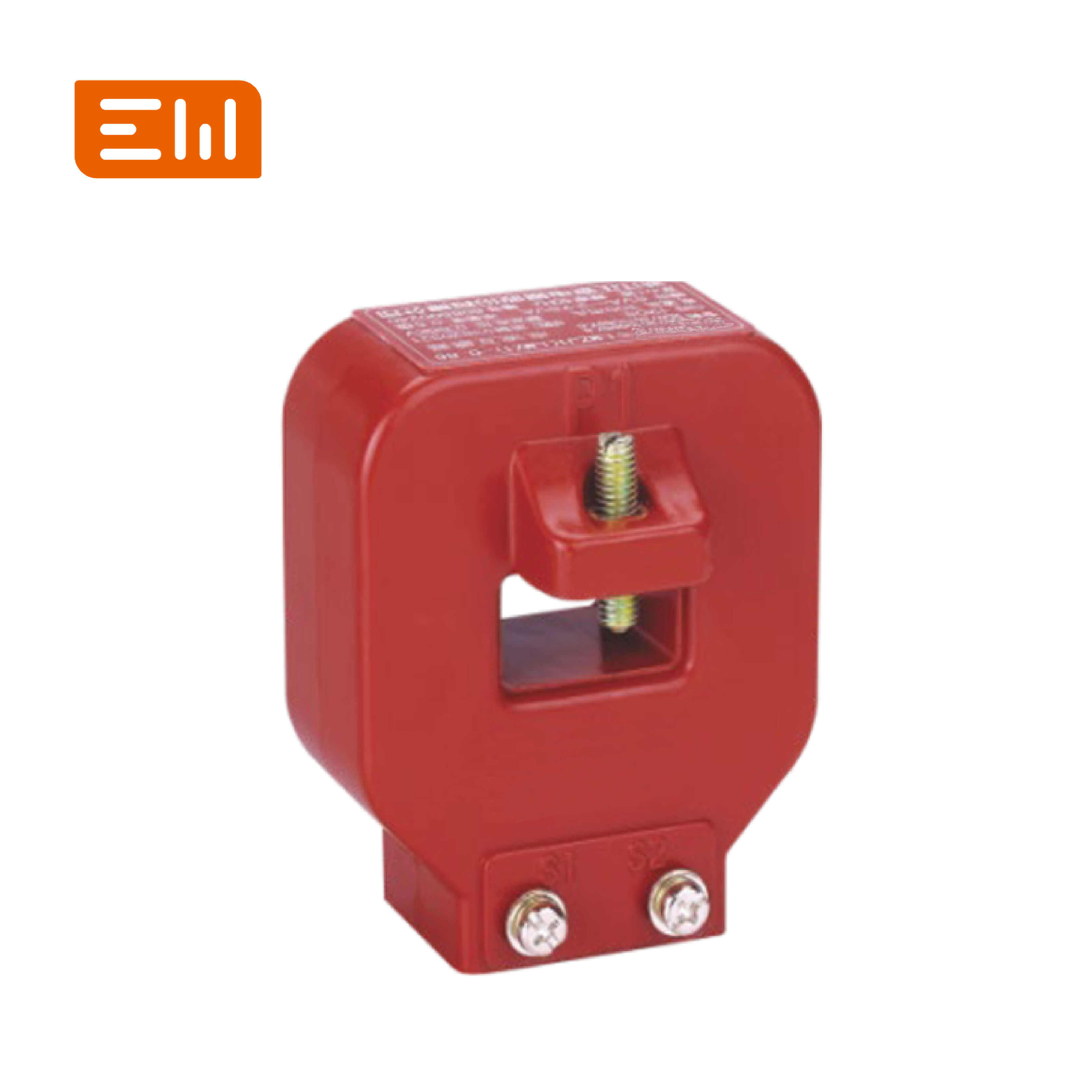
Common CT Wiring Diagrams: Metering, Differential, and Earth Fault
CT wiring errors are a leading cause of commissioning delays and protection misoperations. Polarity, phase association, and correct connections for earth fault or differential schemes must be verified before energization.
This article provides a practical overview of common CT wiring concepts used in metering and protection panels.
Polarity Basics (P1/P2 and S1/S2)
CT polarity defines the direction relationship between primary current and secondary current. Correct polarity is essential for:
- power and energy direction
- directional protection elements
- differential protection stability
Always follow CT markings and verify polarity during commissioning tests.
Metering CT Wiring (Conceptual)
For metering, CT secondaries are wired to meters or transducers with:
- shorting links for safe maintenance
- clear phase labeling
- consistent secondary grounding practice per standard
Residual (Summation) Connections for Earth Fault
Earth fault detection can use residual current derived from three phase CTs (summation) depending on scheme. The key is consistent polarity and correct summation so the relay sees residual current when earth fault occurs.
Earth fault behavior depends on system grounding method, so coordinate wiring and relay settings with the grounding philosophy.
Differential Protection Considerations
Differential schemes compare currents from CTs on two sides of a protected zone. Common pitfalls include:
- incorrect CT polarity on one side
- ratio mismatch between CTs
- unequal CT saturation performance
- incorrect phase mapping
When differential protection is used, CT selection and wiring should be reviewed by a protection engineer, and commissioning tests should validate the scheme.
Commissioning Tips
- perform polarity tests and document results
- verify phase association from primary to relay inputs
- confirm shorting links and terminal tightness
- validate relay scaling and direction before energization
Internal Links
CT category: Current Transformers.
Switchgear where CT wiring is applied: Switchgear.
Conclusion
CT wiring is simple in concept but unforgiving in practice. If you verify polarity, phase mapping, and scheme-specific connections for earth fault and differential protection, you avoid the most common commissioning failures and improve protection dependability.
Image Suggestions
- Image: https://www.enweielectric.com/products/current-transformers
- ALT: "CT wiring concepts for metering, earth fault, and differential protection"
- Image: https://www.enweielectric.com/products/switchgear
- ALT: "Protection relay wiring panel using CT inputs"