
 EN
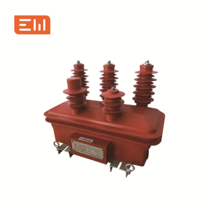
A current transformer (CT) measures current; a voltage transformer (VT), also called a potential transformer (PT), measures voltage. Both provide scaled signals for metering and protection, but their ratios, connection requirements and selection criteria differ. A power transformer that supplies a load is a different product category.
This guide compares conventional CTs and VTs for commercial and industrial distribution projects. Electronic sensors and low-power instrument transformers require their own interface specifications.
What a CT Does
A current transformer (CT) steps down primary current to a standard secondary current (often 1A or 5A). CT outputs feed meters and protection relays to measure and respond to current conditions.
Key safety rule: never open-circuit an energized CT secondary.
What a VT Does
A voltage transformer (VT) steps down primary voltage to a standardized secondary voltage. VT outputs feed meters and protection relays for voltage-based functions.
VT circuits typically require correct primary protection and careful secondary wiring to maintain measurement integrity.
CT vs VT: Core Differences
| Item | CT | VT |
|---|---|---|
| Measures | Current | Voltage |
| Typical secondary | 1A / 5A (or specified outputs) | 100V / 110V / 120V (typical) |
| Main risks | Open-circuit secondary hazard; saturation under faults | Overvoltage if miswired; fusing and insulation constraints |
| Selection focus | Ratio, class, burden, saturation performance | Ratio, class, burden, insulation level, mounting type |
Typical Applications in MV Systems
- Metering: CT + VT provide current and voltage to calculate power and energy.
- Protection: CTs support overcurrent/earth fault; VTs support undervoltage/overvoltage and directional elements.
- Monitoring: power quality and disturbance recording often require both.
Wiring Overview (High Level)
For most projects, you should ensure:
- CT secondaries include shorting links and correct polarity/phase association.
- VT circuits include appropriate protection, isolation, and consistent secondary grounding as required by standards.
Always follow the switchgear and relay manufacturer wiring guidance and local safety standards.
Match the Instrument Transformer to the Application
CT category: Current Transformers.
VT category: Voltage Transformers.
Conclusion
CTs and VTs are the foundation of MV metering and protection. The fastest way to choose correctly is to define the application, confirm the ratio and accuracy needs, and calculate realistic burden including wiring. When CT and VT specs are aligned, commissioning becomes simpler and protection performance becomes more dependable.
CT and VT RFQ Checklist
Send a coordinated schedule rather than requesting a ratio alone. For each device, identify the installation location and the meter or protection function it serves.
- System voltage, frequency, insulation requirements and indoor or outdoor service.
- CT primary and secondary currents, number of cores, metering or protection duty, required accuracy and burden for each core.
- VT primary and secondary voltages, winding connections, metering or protection duty, accuracy and burden for each secondary.
- Meter and relay models, secondary cable routes, mounting dimensions, terminal arrangement and project drawings.
- Applicable utility requirements and the test documents required for the offered configuration.
Check the medium-voltage CT range and VT options against the project schedule. A category name does not establish suitability for a particular relay or installation.
Frequently Asked Questions
Is a potential transformer the same as a voltage transformer?
PT and VT commonly refer to the voltage-measuring instrument transformer. Confirm the actual ratio, winding arrangement and application in the supplier documentation.
Can a CT replace a VT?
No. They measure different quantities and use different connections. Select each against its metering or protection function.
Should metering and protection share the same CT core?
Do not assume that they can. The core arrangement and performance must satisfy the connected equipment and the approved protection design.
To discuss a project, send Enwei Electric your CT/VT schedule and single-line diagram. Request a proposal with clearly stated ratings, interfaces and supporting documents.
Updated 31 October 2026.