
 EN
EN
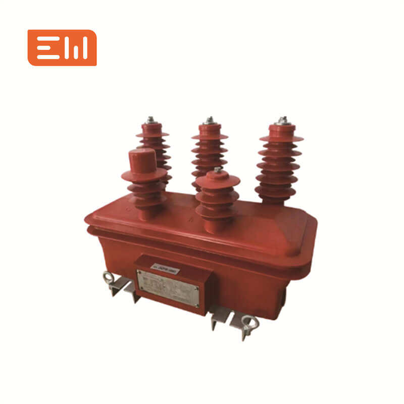
CT Accuracy Class and Burden Explained (0.2, 0.5, 1.0, 5P, 10P)
CT specifications can look intimidating, but two terms drive most performance outcomes: accuracy class and burden. If either is mismatched, meters read wrong and protection relays may misoperate during faults.
This guide explains what CT accuracy class and burden mean in practical terms, and how to select the right CT for metering or protection.
What “Accuracy Class” Means for Metering CTs
Metering CT accuracy classes such as 0.2, 0.5, and 1.0 indicate allowable measurement error within defined operating ranges and burdens. In general:
- 0.2: higher accuracy applications where tighter measurement error is required.
- 0.5: common for many metering and monitoring needs.
- 1.0: typically acceptable for less demanding monitoring.
Always confirm the standard and the current range over which the class is guaranteed for your project.
Protection CT Classes (5P, 10P) and What They Indicate
Protection CTs use classes like 5P or 10P with additional parameters that relate to fault current performance (avoiding early saturation). The goal is not perfect accuracy at normal load, but dependable behavior when current rises rapidly during faults.
Protection CT selection must match the fault level and the relay requirements, especially for schemes like differential protection.
What Is CT Burden?
Burden is the load connected to the CT secondary circuit, usually expressed in VA at rated secondary current. Burden includes:
- Meter or relay input burden
- Wiring resistance (often underestimated)
- Terminal blocks and additional devices
If burden is higher than the CT rating, the CT may not meet its accuracy class and may saturate earlier under fault conditions.
How Wiring Increases Burden (Practical Insight)
Long secondary wiring runs add resistance. At 5A secondary, wiring losses can become significant in long runs. Many projects choose 1A secondaries to reduce wiring losses and improve overall performance when secondary runs are long.
When specifying CTs, include a realistic estimate of cable length and conductor size in the burden calculation.
How to Choose the Right CT Class (Simple Decision Path)
- Billing / revenue metering: select a metering accuracy class aligned with local requirements and verify burden margin.
- General monitoring: choose a class that matches monitoring objectives, with adequate burden rating.
- Protection relays: select a protection CT class and performance suitable for the network fault level and relay scheme.
Do not use a “metering” CT for protection without verifying saturation performance and relay requirements.
Common Specification Mistakes
- Ignoring wiring: burden calculation only includes the relay, not the wiring.
- Over-sizing ratio: choosing too high a ratio reduces resolution at normal load.
- Wrong CT for protection: early saturation makes relays under-read fault current.
- Mixing standards: inconsistent class definitions between standards and project documentation.
Internal Links
CT category: Current Transformers.
For VT and complete metering sets: Voltage Transformers.
Conclusion
CT accuracy class tells you how the CT should perform, and burden tells you whether it can perform that way in your installation. If you match CT class to application (metering vs protection) and plan burden realistically (including wiring), you avoid the most common CT-related errors.
Image Suggestions
- Image: https://www.enweielectric.com/products/current-transformers
- ALT: "CT accuracy class and burden selection for metering and protection"
- Image: https://www.enweielectric.com/products/switchgear
- ALT: "MV switchgear metering cubicle using CTs and VTs"
Table of Contents
- CT Accuracy Class and Burden Explained (0.2, 0.5, 1.0, 5P, 10P)
- What “Accuracy Class” Means for Metering CTs
- Protection CT Classes (5P, 10P) and What They Indicate
- What Is CT Burden?
- How Wiring Increases Burden (Practical Insight)
- How to Choose the Right CT Class (Simple Decision Path)
- Common Specification Mistakes
- Internal Links
- Conclusion
- Image Suggestions