
 EN
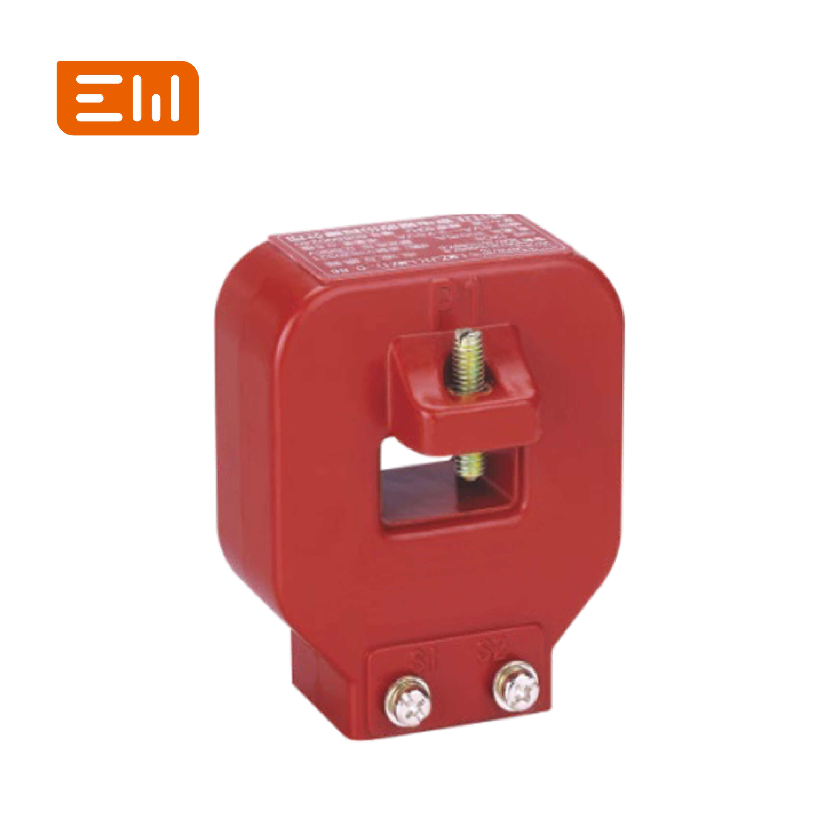
CT Saturation and Knee Point: What Protection Engineers Need to Know
In protection systems, a CT is not just a measurement device. During faults, CT performance can determine whether relays trip correctly. The key risk is CT saturation, where the CT core can no longer reproduce the primary current waveform accurately in the secondary circuit.
This article explains saturation, the “knee point” concept, and practical steps to reduce misoperations.
What Is CT Saturation?
CT saturation happens when the magnetic core reaches a point where increasing primary current no longer results in a proportional secondary current. The CT requires more magnetizing current, distorting the secondary waveform and reducing its magnitude.
When the secondary current is distorted or reduced, protection relays may “see” less fault current than is actually present.
Why CT Saturation Matters for Protection Relays
During short circuits, the primary current can rise to many times rated current. If the CT saturates early:
- Overcurrent relays may operate slower or fail to trip at expected thresholds.
- Differential protection may misoperate due to unequal saturation between CTs.
- Earth fault protection can become unreliable if residual currents are distorted.
The result can be larger equipment damage, longer outages, and complicated post-fault analysis.
Knee Point: A Practical Concept
The knee point is often used to describe the point on the CT excitation curve where a small increase in secondary voltage requires a large increase in magnetizing current. In practical terms, it indicates how much secondary voltage the CT can develop before it drives into heavy core saturation.
Higher knee point capability generally supports better protection performance for demanding schemes, especially where secondary circuit burden is high.
Factors That Push a CT Toward Saturation
- High fault current: higher system fault levels require stronger CT performance.
- High burden: long wiring runs and relay inputs require more secondary voltage.
- DC offset: asymmetrical fault currents increase saturation risk.
- Incorrect ratio selection: very high ratios reduce usable performance in some scenarios.
How to Reduce Saturation Risk (Practical Steps)
- Choose protection-class CTs matched to the fault level and relay scheme.
- Control burden: shorten wiring runs, use appropriate conductor size, and account for all devices.
- Consider 1A secondaries when wiring runs are long to reduce burden.
- Specify CT performance appropriately for differential schemes and high-speed protection.
The best approach is to coordinate CT selection with the protection engineer who sets relay settings and reviews fault studies.
Commissioning and Troubleshooting Clues
If protection performance is inconsistent, investigate:
- Unexpected burden: added devices or longer wiring than assumed.
- Loose secondary connections: increased resistance and erratic signals.
- CT polarity errors: can create differential misoperations.
- Incorrect CT class or ratio compared with the design documents.
Internal Links
CT product categories: Current Transformers.
For MV panels integrating CTs and protection: Switchgear.
Conclusion
CT saturation is one of the most common hidden causes of protection problems. If you match CT performance to fault level and burden, and validate installation quality, you dramatically reduce the risk of relays under-reading faults or misoperating during disturbances.
Image Suggestions
- Image: https://www.enweielectric.com/products/current-transformers
- ALT: "Protection-class current transformers designed to reduce saturation"
- Image: https://www.enweielectric.com/products/switchgear
- ALT: "MV switchgear protection cubicle using CT signals for relays"
Table of Contents
- CT Saturation and Knee Point: What Protection Engineers Need to Know
- What Is CT Saturation?
- Why CT Saturation Matters for Protection Relays
- Knee Point: A Practical Concept
- Factors That Push a CT Toward Saturation
- How to Reduce Saturation Risk (Practical Steps)
- Commissioning and Troubleshooting Clues
- Internal Links
- Conclusion
- Image Suggestions