
 EN
EN
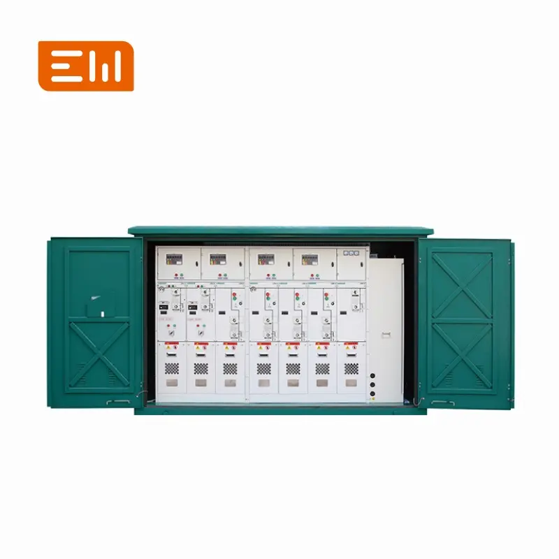
RMU Cable Termination Options: Elbows, Bushings, and Safety Interlocks
In RMU projects, cable termination interfaces cause more delays than almost any other detail. Two RMUs can have the same voltage class and fault duty but still be incompatible due to connector interface, bushing style, or clearance constraints in the cable compartment.
This guide explains common RMU cable termination options and the specification items that prevent field rework.
Why Cable Interfaces Matter in MV RMUs
RMU cable terminations must handle:
- Electric field stress: especially near interfaces and insulation transitions
- Environmental exposure: condensation, contamination, and corrosion
- Mechanical constraints: bending radius, pulling forces, and compartment space
- Safety procedures: voltage presence indication, test points, and earthing
Common Termination Concepts
Depending on the RMU design and region, you may see:
- Separable connectors (elbows): commonly used for compact RMUs; enable safe, standardized connection methods.
- Fixed bushings/terminals: used in some designs; may require different termination kits and installation practices.
- Rear or front cable access: affects civil design and clearance planning.
Instead of naming the termination generically, specify the interface standard or connector system required by your project.
Test Points and Voltage Indication
Many MV procedures require confirmation of voltage absence before access. Depending on the design, specify:
- Capacitive test points for voltage indication
- Voltage presence indicators and compatibility with your test equipment
- Earthing provisions and safe sequence to earth the cable
Safety Interlocks and Access Control
Cable compartments should include interlocks that support safe operations. In RFQs, clarify:
- Access interlocks: prevention of opening cable compartment when circuit is live
- Earthing switch interlock: ability to apply earth before access
- Key interlocks: utility operating procedure alignment
What to Specify in Your RFQ
- Cable type and size: conductor cross-section and insulation type
- Interface system: connector/bushing standard, test points, and plug-in requirements
- Cable entry: bottom/top; gland plate details; sealing expectations
- Clearances: minimum bending radius and installation access space
- Compartment IP: especially for outdoor kiosks
Installation Tips (Field Practical)
- Plan cable routing early: avoid sharp bends that stress terminations.
- Control moisture: seal cable entries and verify heaters where needed.
- Label phases and screens: reduce commissioning mistakes.
- Verify torque: use correct torque for connector interfaces.
Internal Links
RMU category page: Ring Main Units.
Related MV panels: Switchgear.
Conclusion
RMU cable terminations are a high-risk interface if not specified clearly. If you define the connector/bushing system, test point requirements, compartment access constraints, and IP expectations, you can avoid the most common installation delays and commissioning surprises.
Image Suggestions
- Image: https://www.enweielectric.com/products/rmu
- ALT: "RMU cable termination interface with separable connectors"
- Image: https://www.enweielectric.com/products/voltage-transformers
- ALT: "Voltage indication and metering devices used in MV panels"
Table of Contents
- RMU Cable Termination Options: Elbows, Bushings, and Safety Interlocks
- Why Cable Interfaces Matter in MV RMUs
- Common Termination Concepts
- Test Points and Voltage Indication
- Safety Interlocks and Access Control
- What to Specify in Your RFQ
- Installation Tips (Field Practical)
- Internal Links
- Conclusion
- Image Suggestions